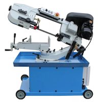
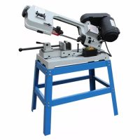
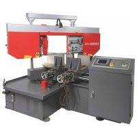
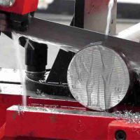
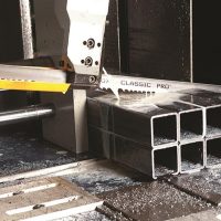
A sawing machine uses tools such as circular saw blades, bandsaw blades, or hacksaw blades to cut metal materials like round bars, square bars, pipes, and profiles. Known for high machining accuracy, these machines are primarily used in stock preparation workshops for cutting various bar stock, pipes, and other profiles. The blade is driven by a driving wheel and a driven wheel, while the cutting direction is controlled by a guide rail control frame. The blade is aligned and straightened via adjusting self-aligning bearings, and chips are removed by a chip scraper. A hydraulic cylinder piston rod supports the guide rail control frame for the downward feed motion during cutting. The bandsaw machine is equipped with manual or hydraulic cylinder workpiece clamping/locking mechanisms, as well as hydraulic control valve switches, among other components.
Mechanical Structure of Metal Sawing Machines
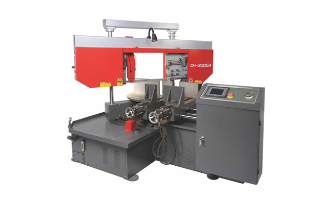
The main components of a sawing machine include: the base; bed and column; saw beam and transmission mechanism; guide device; workpiece clamping device; tensioning device; feed frame; hydraulic transmission system; electrical control system; lubrication and cooling system.
Base
The base is a box-shaped structure welded from steel plates. The bed and column are fixed onto it. The inner cavity of the base provides substantial space. The front left side houses the electrical button control box, the right side contains the electrical distribution panel box, and the center consists of a hydraulic oil tank welded from steel plates, containing the hydraulic pump unit and hydraulic pipelines. The right side contains the cooling/cutting fluid tank and pump. The four corners have holes for foundation bolts.
Bed
The bed is a cast iron component fixed on the base. The column consists of one large and one small cylinder. The large cylindrical column serves as the guide rail for the movement of the saw frame, supporting the up-and-down movement of the saw beam and ensuring precise guidance. The small cylinder plays an auxiliary role, ensuring normal cutting by the blade. The center section houses the material clamping vise and the manual feeding mechanism. A worktable for receiving finished pieces is connected in front of the vise. The left clamping device features a clamping screw rod passing through the hole of the hydraulic clamping cylinder rod. Rotating the handwheel or pressing a button moves the left jaw left or right.
Saw Beam and Transmission Mechanism
This is formed by cutting and welding thick steel plates, offering substantial rigidity. A worm gearbox is fixed on its right rear side. The worm gear inside the box is fixed to the driving wheel on the saw beam, allowing synchronous rotation. The left side houses the driven wheel and the blade tensioning mechanism. The rotary motion of the blade is achieved by the main motor, pulley, and worm gear set, which transmits power to the driving wheel through a two-stage speed change. The driving wheel and the blade then drive the driven wheel. The blade speed typically has three gears (this may vary by machine; some machines adjust the bandsaw speed via a frequency converter).
Blade Guide Device
Installed on the saw beam support plate, the guide device consists of left and right guide arms and guide heads. Both the left and right guide arms can move along dovetail tenons (or the right guide arm may be fixed on the column sleeve). The distance between the two guide arms is adjusted to be about 40mm wider than the workpiece size. This device adjusts the installation angle of the blade to ensure it is perpendicular to the worktable. To guarantee cutting accuracy and reduce vibration, each guide arm is equipped with a set of guide wheels (rolling bearings) and wear-resistant guide blocks. There are also wear-resistant alloy guide blocks for the back of the blade.
Clamping Mechanism
The right vise is fixed on the bed. The clamping screw rod passes through the hole of the hydraulic clamping cylinder. The left vise is connected via the screw rod and moves left and right along guides. When the left vise is 10-30mm from the workpiece, pressing the “Clamp Tighten” or “Clamp Loosen” button on the control panel activates the hydraulic cylinder to clamp or release the workpiece.
Tensioning Device
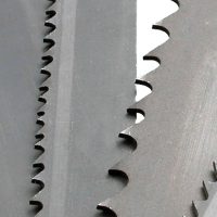
The tensioning device consists of a slide seat, slide plate, screw rod, etc. To tension the blade, use a torque wrench to rotate clockwise, putting the blade into a tensioned, working state. If the machine is to be shut down for an extended period, rotate the torque wrench counterclockwise to loosen the blade, allowing for replacement.
Working Principle
The hydraulic transmission system, composed of pumps, valves, cylinders, oil tanks, pipelines, and other components, completes the lifting/lowering of the saw beam and the clamping of the workpiece under electrical control. The feed rate can be steplessly adjusted via a flow control valve to meet the cutting needs for different material workpieces. The electrical control system, consisting of an electrical cabinet, control box, junction box, limit switches, solenoids, etc., forms a control circuit that manages blade rotation, saw beam movement, workpiece clamping, etc., according to set procedures to achieve a normal cutting cycle.
Lubrication System
Before starting the machine, lubricate according to the requirements for the machine’s lubrication points (wire brush shaft, worm gearbox, driving wheel bearing seat, worm bearing, upper and lower shafts of the lifting cylinder, sliding surface of the movable vise, clamping screw rod). The worm and worm gear inside the worm gearbox are lubricated by an oil bath using No. 30 engine oil, injected through the oil plug hole on the top of the gearbox. The outside of the box has an oil level gauge. When the saw beam is at its lowest position, the oil level should be between the upper and lower limits of the gauge. Change the oil after the first month of use, and subsequently every 3-6 months. The bottom of the worm gearbox has an oil drain plug.
Blade Drive Motion
The motor mounted on the worm gearbox drives the worm and worm gear inside via a pulley and V-belt, which in turn rotates the driving wheel. This drives the blade looped around the driving and driven wheels for the cutting rotary motion.
Blade Feed Motion
The feed motion is controlled by a hydraulic system comprising the lifting cylinder and a speed control valve, which regulates the descent speed of the saw beam, thereby controlling the feed rate of the blade (steplessly adjustable).
Chip Brush Rotation
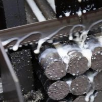
Located where the blade exits the cut, the chip brush rotates in the direction of the blade movement. It is supplied with coolant by the coolant pump to clean chips from the blade teeth. The coolant is stored in the tank on the right side of the base and delivered directly by the pump.
Operation Sequence
Press the start button (or rotate it clockwise) to start the oil pump motor and gear pump. Hydraulic oil enters the pipelines through a filter. Adjust the relief valve to set the system working pressure as required. Pressing the stop button (inward) stops all motors.
Workpiece Clamping: Press the “Clamp Tighten” button. The solenoid valve activates, directing hydraulic oil to the left side of the clamping cylinder (right side oil returns to the tank), moving the left jaw to clamp the workpiece.
Saw Beam Descent (Working Feed): Press the “Work” button. Hydraulic oil enters the rod cavity of the lifting cylinder via the solenoid valve. Oil from the non-rod cavity returns to the tank through the solenoid valve and the one-way flow control valve, controlling the feed rate.
Saw Beam Rapid Descent: Press the “Descent” button. The solenoid valve activates, directing oil into the rod cavity of the lifting cylinder. Oil from the non-rod cavity returns directly to the tank via the solenoid valve, causing rapid descent.
Saw Beam Ascent: Press the “Ascent” button. Hydraulic oil enters the non-rod cavity of the lifting cylinder via the solenoid valve. Oil from the rod cavity returns to the tank through the solenoid valve.
Workpiece Unclamping: Press the “Clamp Loosen” button. Hydraulic oil enters the right side of the clamping cylinder via the solenoid valve. Oil from the left side returns to the tank through the solenoid valve, moving the left jaw leftward to release the workpiece.